ZLX-ESP32-1 / ESP32-2432S0248R-PLUS
2.8-inch Resistive Touch Display Development Board
Product Overview
ESP32-2432S0248R-PLUS is a 2.8-inch color touch display development board based on the ESP32-WROOM-32UE wireless module. It integrates LCD display, touch input, TF card, USB Type-C, UART, battery port and multiple expansion interfaces. It is suitable for IoT display terminals, smart home control, HMI panels, education and embedded development.
Key Specifications
| Item | Specification |
|---|---|
| Model | ZLX-ESP32-1 |
| Main Module | ESP32-WROOM-32UE |
| Wireless | 2.4GHz Wi‑Fi 802.11 b/g/n; Bluetooth / BLE |
| Display | 2.8-inch TFT LCD, 240 × 320 |
| Touch | Resistive touch, XPT2046 |
| LCD Driver | ST7789 with BGR color order initialization |
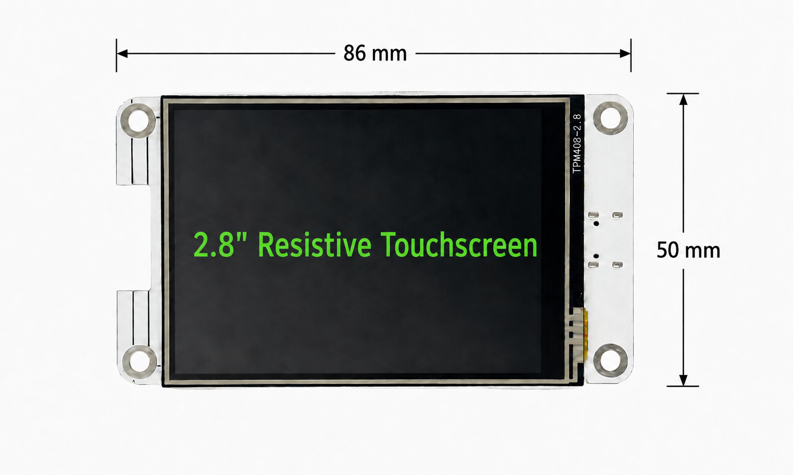
| Board Size | 86 mm × 50 mm |
| Power | USB Type‑C 5V input; external 3.3V battery port |
| Logic Level | 3.3V |
ESP32-WROOM-32UE Module Parameters
| Item | Specification |
|---|---|
| CPU Core | Xtensa dual-core 32-bit LX6 |
| Clock Frequency | Up to 240MHz |
| ROM | 448KB |
| SRAM | 520KB |
| RTC SRAM | 16KB |
| Flash | Typical board configuration: 4MB; actual batch may vary |
| Wi‑Fi | 2.4GHz, 802.11 b/g/n |
| Bluetooth | Bluetooth BR/EDR and BLE |
| Antenna | On-board PCB antenna |
| Operating Voltage | Module 3.0V to 3.6V; board logic 3.3V |
| Module Size | 18.0mm × 25.5mm × 3.1mm |
Display and Touch Notes
This board uses a 2.8-inch resistive touch display with XPT2046 touch controller. The LCD driver is ST7789 and should be initialized with BGR color order.
If red and blue colors are swapped, please check the TFT_RGB_ORDER / BGR initialization setting.
Recommended Initialization
// TFT display / ST7789
#define ST7789_DRIVER
#define TFT_WIDTH 240
#define TFT_HEIGHT 320
#define TFT_MISO 12
#define TFT_MOSI 13
#define TFT_SCLK 14
#define TFT_CS 15
#define TFT_DC 2
#define TFT_RST -1
#define TFT_BL 21
#define TFT_BACKLIGHT_ON HIGH
#define TFT_RGB_ORDER TFT_BGR
// Touch / XPT2046
#define TOUCH_IRQ 36
#define TOUCH_MISO 39
#define TOUCH_MOSI 32
#define TOUCH_CS 33
#define TOUCH_CLK 25
Interface Overview
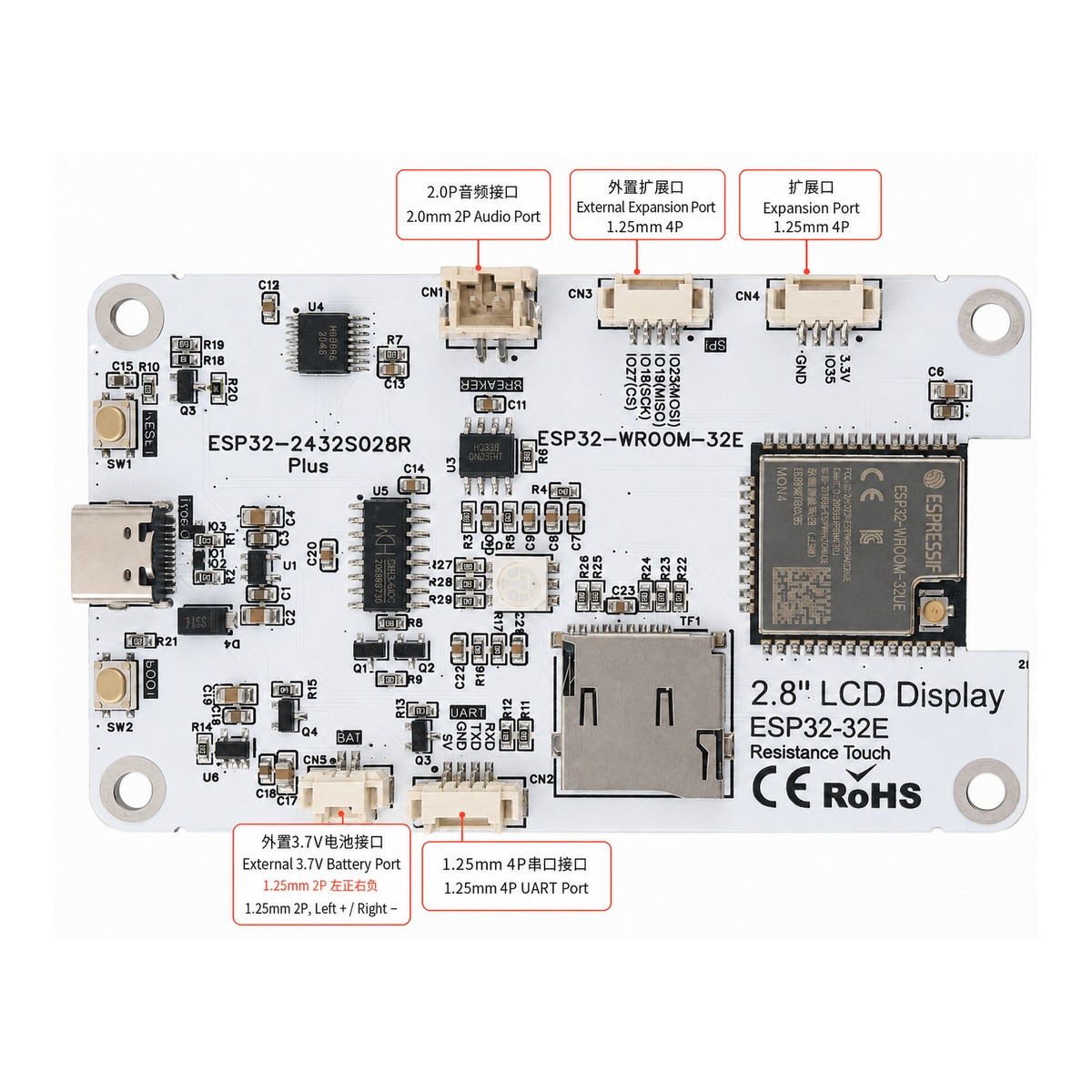
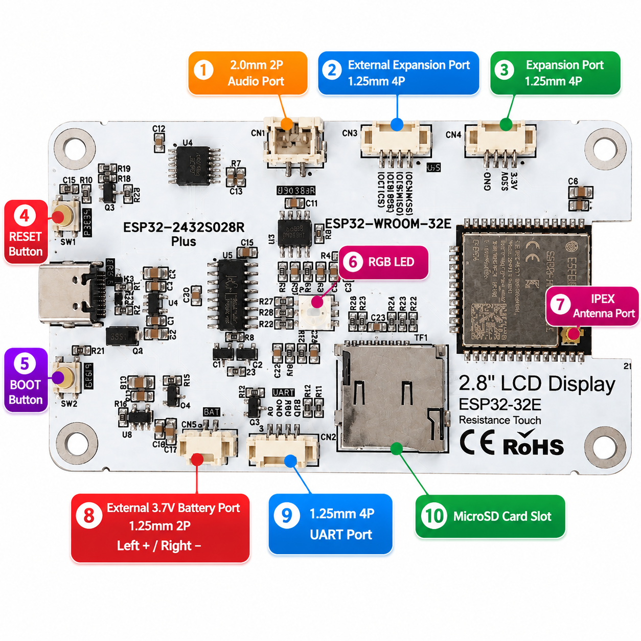
- 2.0P Audio Port: Reserved for audio input/output or amplifier-related expansion.
- External Expansion Port: Reserved for SPI / GPIO peripherals, sensors or custom modules.
- Expansion Port: Provides 3.3V, GND and GPIO signals for low-power external modules.
- External 3.3V Battery Port: 1.25P connector, left + / right -. Do not reverse polarity or input 5V.
- 1.25P UART Port: Used for UART communication and debugging.
- TF Card Slot: For data, image or configuration storage.
GPIO Mapping (Mobile-Friendly Card Layout)
The original two-page GPIO mapping table has been merged and redesigned into cards for easier reading on mobile devices.
LCD / ST7789 Display Display SPI and backlight control | ||||||||||||||||||||||||||||
| ||||||||||||||||||||||||||||
Touch / XPT2046 Resistive touch controller interface | ||||||||||||||||||||
| ||||||||||||||||||||
Battery Detection Battery voltage sensing | ||||
| ||||
RGB LED On-board status indicator | ||||||||||||
| ||||||||||||
Audio Audio input and amplifier enable | ||||||||
| ||||||||
Expansion SPI External module chip select | ||||
| ||||
TF Card MicroSD / TF card SPI interface | ||||||||||||||||
| ||||||||||||||||
Package Contents
- Development board ×1
- USB Type‑C data cable ×1
- IPEX1-to-SMA adapter ×1
- 3 dBi rubber duck antenna ×1
Important Notes
- GPIO logic level is 3.3V. Do not connect 5V signals directly.
- GPIO34, GPIO36 and GPIO39 are input-only pins and cannot be used as normal outputs.
- The external 3.3V battery port is left + / right -. Do not reverse polarity and do not input 5V.
- Recalibrate touch after display rotation or coordinate direction changes.
- If colors are swapped, check the ST7789 BGR/RGB initialization setting.
Typical Applications
- Smart home control panel
- IoT data display terminal
- Industrial equipment status display
- Sensor data display
- Wi‑Fi / Bluetooth control terminal
- Educational development board
Technical Support
Development resources, sample programs, firmware, GPIO mapping table and update files are available at:
Resource Download: https://www.zlxchina.com/
Copyright © Hefei Zhilu Xing Information Technology Co., Ltd.