ZLX-ESP32-2
ESP32-C5 2.8-inch Touch Display Development Board
中英文使用者說明書 / Bilingual User Manual
Model / 型號: ZLX-ESP32-2
Module / 模組: ESP32-C5-WROOM-1U-N8R8
Document Version / 文件版本: V1.1 | 2026-08-25
1. 產品概述 / 1. Product Overview
ZLX-ESP32-2 是一款基於 ESP32-C5-WROOM-1U-N8R8 模組的 2.8 吋電阻式觸控螢幕開發板,整合彩色 LCD、XPT2046 觸摸、microSD/TF 卡槽(僅提供卡槽,不含 microSD/TF 卡)、GPS 介面、音訊輸出、電池電壓偵測、綠色 LED、BOOT/RESET 按鍵及外接天線接口。適合 Wi-Fi 6、Bluetooth LE、Zigbee/Thread、人機介面、數據記錄及物聯網應用開發。
ZLX-ESP32-2 is a 2.8-inch resistive-touch development board based on the ESP32-C5-WROOM-1U-N8R8 module. It integrates a color LCD, XPT2046 touch controller, a microSD/TF card slot (slot only; no microSD/TF card is included), GPS interface, audio output, battery-voltage sensing, green LED, BOOT/RESET buttons, and an external-antenna connector. It is suitable for Wi-Fi 6, Bluetooth LE, Zigbee/Thread, HMI, data logging, and IoT development.
主要特點 / Key Features
ESP32-C5 32 位元 RISC-V 單核心處理器,最高 240 MHz / ESP32-C5 32-bit RISC-V single-core CPU, up to 240 MHz
ESP32-C5-WROOM-1U-N8R8:8 MB Flash + 8 MB PSRAM(模組板載資源,不是 microSD/TF 卡) / ESP32-C5-WROOM-1U-N8R8: 8 MB Flash + 8 MB PSRAM (onboard module memory, not a microSD/TF card)
2.4 GHz + 5 GHz 雙頻 Wi-Fi 6(802.11ax) / 2.4 GHz + 5 GHz dual-band Wi-Fi 6 (802.11ax)
Bluetooth LE、IEEE 802.15.4、Zigbee 3.0、Thread 1.4 / Bluetooth LE, IEEE 802.15.4, Zigbee 3.0, Thread 1.4
2.8 英吋 240×320 LCD,ST7789 驅動,BGR 初始化,不開啟反色 / 2.8-inch 240×320 LCD, ST7789 driver, BGR initialization, display inversion disabled
XPT2046 電阻式觸控控制器 / XPT2046 resistive touch controller
LCD 與 TF 卡共用 SPI 總線,獨立 CS;觸控使用獨立軟體 SPI / LCD and TF card share SPI with separate CS; touch uses an independent software SPI
闆卡尺寸約 86 mm × 50 mm / Board size approx. 86 mm × 50 mm
IPEX1 外接天線介面;使用無線功能前需正確連接外接天線 / IPEX1 external antenna connector; connect a suitable external antenna before radio use
適用對象 / Intended Users
適用於嵌入式開發者、物聯網開發者、創客、教學實驗及產品原型設計。
For embedded developers, IoT developers, makers, education/lab use, and product prototyping.
2. 外觀與尺寸 / 2. Appearance and Dimensions
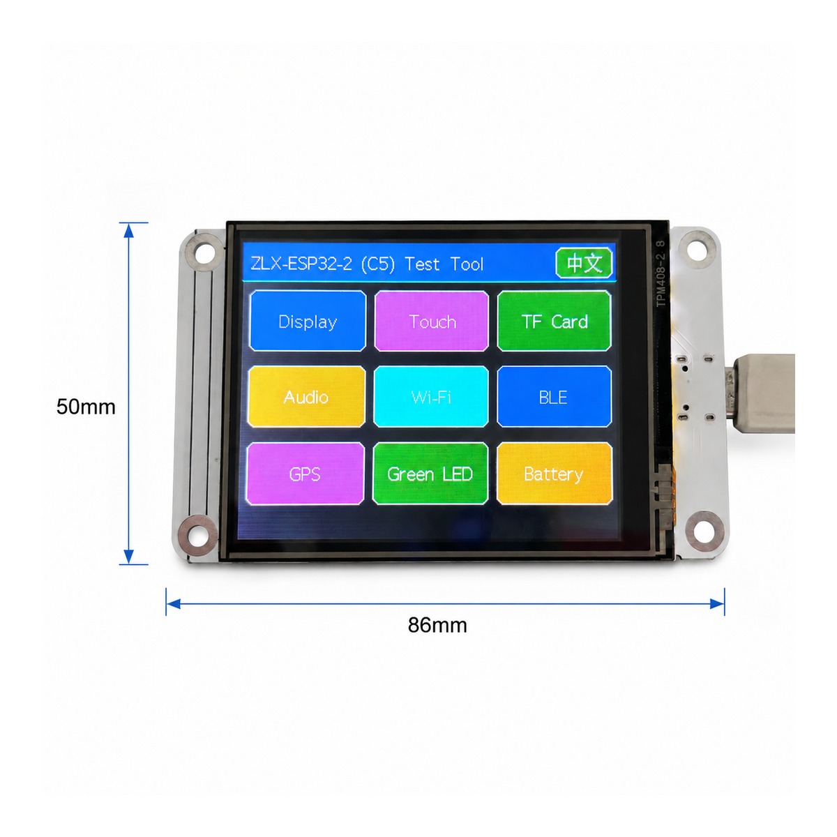
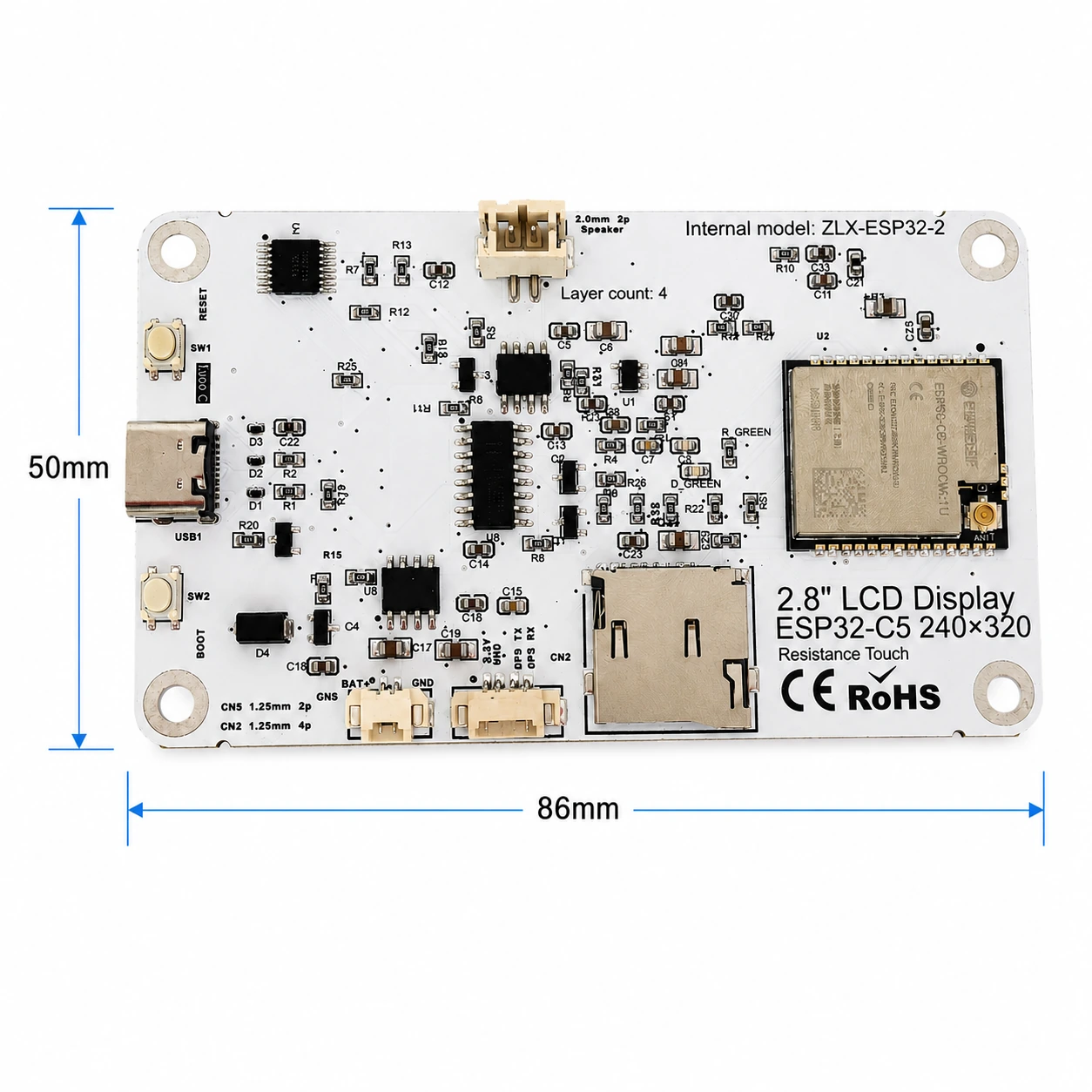
闆卡外形尺寸約為 86 mm × 50 mm。以下正反面圖片用於識別螢幕、介面與主要裝置。
The board outline is approximately 86 mm × 50 mm. The images below help identify the display, connectors, and major components.
|
|
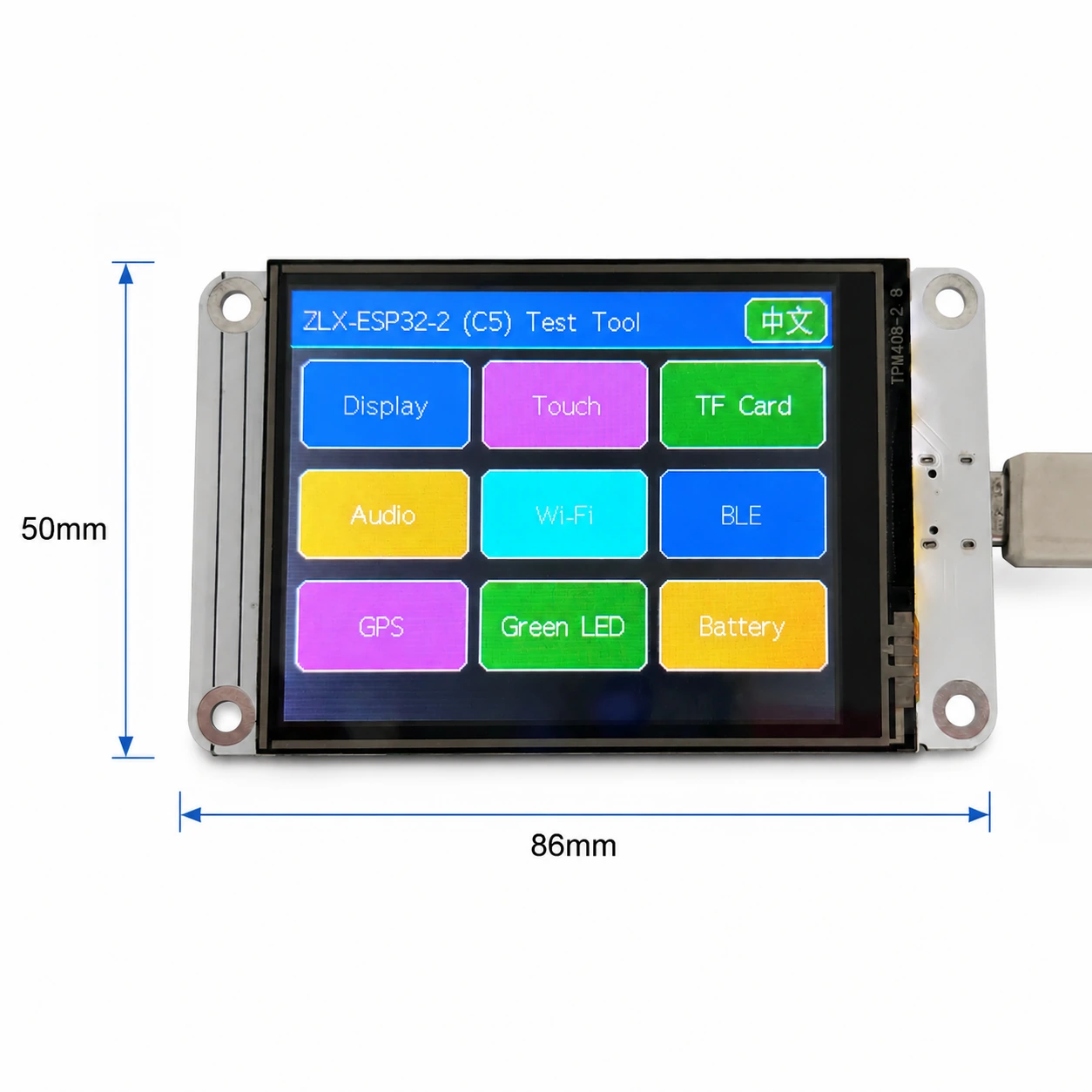
圖 1 正面與螢幕面尺寸示意 / Figure 1 Board front and display-side dimensions
介面標註 / Connector Identification
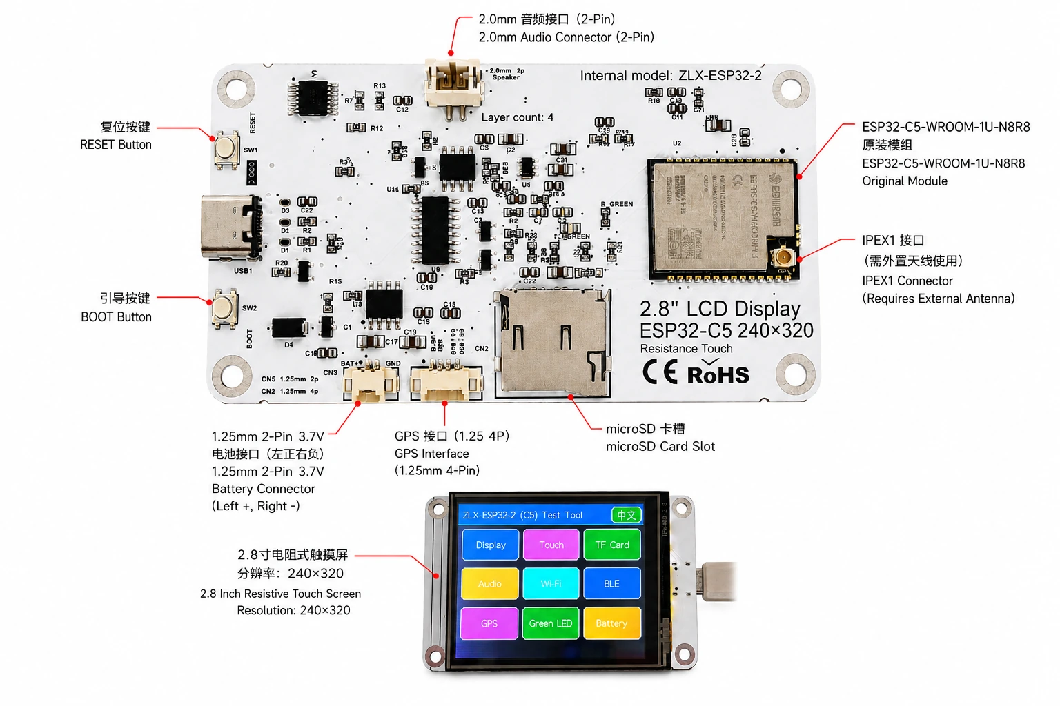
圖 2 ZLX-ESP32-2 中英文介面標註 / Figure 2 Bilingual connector identification
3. 開發板規格 / 3. Board Specifications
專案 / Item | 規格 / Specification |
開發板型號 / Board model | ZLX-ESP32-2 |
核心模組 / Core module | ESP32-C5-WROOM-1U-N8R8 |
闆卡尺寸 / Board size | Approx. 86 × 50 mm |
顯示螢幕 / Display | 2.8-inch TFT LCD, ST7789, 240×320 native resolution |
顏色順序 / Color order | BGR initialization |
顯示反色 / Display inversion | OFF / Normal display mode(不開反色) |
觸摸 / Touch | Resistive touch / 電阻式觸摸, XPT2046 |
microSD/TF 卡槽 / microSD/TF Card Slot | SPI mode; card not included / SPI 模式;不含卡 |
GPS 介面 / GPS interface | 1.25 mm 4-pin connector; UART signals on GPIO0/GPIO9 |
音訊介面 / Audio | 2.0 mm 2-pin speaker/audio connector; PWM audio + amplifier enable |
電池介面 / Battery | 3.7 V 1S, 1.25 mm 2-pin; protected 1000–3000 mAh recommended / 單節 3.7 V;建議 1000–3000 mAh 附保護板 |
外接天線 / External antenna | IPEX1 connector; required for the WROOM-1U radio path |
按鍵 / Buttons | RESET, BOOT |
狀態指示 / Indicator | Green LED on GPIO26 |
說明 / Note: 螢幕原生解析度為 240×320;軟體設定為橫屏旋轉時,邏輯顯示尺寸可表現為 320×240。 / The panel native resolution is 240×320; in landscape rotation, the logical display size may be 320×240.
4. ESP32-C5-WROOM-1U-N8R8 模組參數 / 4. ESP32-C5-WROOM-1U-N8R8 Module Specifications
以下關鍵參數依據 Espressif 官方 ESP32-C5-WROOM-1 / WROOM-1U Datasheet v1.2。
The following key parameters are based on Espressif's official ESP32-C5-WROOM-1 / WROOM-1U Datasheet v1.2.
專案 / Item | 規格 / Specification |
內建晶片 / Embedded SoC | ESP32-C5HR8 |
CPU | 32-bit RISC-V single core, up to 240 MHz |
ROM | 320 KB |
HP SRAM | 384 KB |
LP SRAM | 16 KB |
Flash | 8 MB Quad SPI |
PSRAM | 8 MB Quad SPI |
Wi-Fi | 1T1R, 2.4 GHz + 5 GHz dual-band; IEEE 802.11ax/ac/b/g/n; up to 150 Mbps |
2.4 GHz 頻率 / Frequency | 2412–2484 MHz |
5 GHz 頻率 / Frequency | 5180–5885 MHz (subject to regional regulations) |
Bluetooth | Bluetooth LE; Espressif v1.2 feature list states Bluetooth Core 6.0 certified |
IEEE 802.15.4 | 2.4 GHz OQPSK, 250 Kbps |
Zigbee / Thread | Zigbee 3.0 / Thread 1.4 |
GPIO | Up to 22 GPIOs at module level |
典型週邊 / Peripherals | GPIO, SPI, UART, I2C, I2S, RMT, LED PWM, USB Serial/JTAG, MCPWM, GDMA, CAN FD, SDIO slave, ADC, temperature sensor, timers, watchdogs, etc. |
模組工作電壓 / Module supply | 3.0–3.6 V, typical 3.3 V |
推薦電源能力 / Recommended supply capability | External supply should be capable of at least 0.6 A for the module |
環境溫度 / Ambient temperature | -40 to +85 °C |
模組尺寸 / Module size | 18.0 × 21.2 × 3.3 mm |
天線 / Antenna | External antenna via connector/module RF path; 50 Ω RF system |
5. 顯示與觸摸 / 5. Display and Touch
LCD 參數 / LCD Parameters
專案 / Item | 規格 / Specification |
尺寸 / Size | 2.8 inch |
驅動 IC / Driver IC | ST7789 |
原生解析度 / Native resolution | 240 × 320 |
橫屏邏輯分辨率 / Landscape logical resolution | 320 × 240 (depending on rotation setting) |
顏色順序 / Color order | BGR |
反色 / Inversion | Disabled / OFF; normal display mode |
SPI 時鐘 / SCK | GPIO6 |
SPI MOSI | GPIO7 |
SPI MISO | GPIO2 (shared with TF card; used if required by library/readback) |
LCD CS | GPIO10 |
LCD Backlight / 背光 | GPIO13 |
LCD DC / RS | GPIO14 |
觸摸參數 / Touch Parameters
觸摸類型:4 線電阻式觸摸;控制器:XPT2046。 / Touch type: 4-wire resistive; controller: XPT2046.
DOUT=GPIO3,SCK=GPIO4,DIN=GPIO5。 / DOUT=GPIO3, SCK=GPIO4, DIN=GPIO5.
CS=GPIO23,IRQ=GPIO25。 / CS=GPIO23, IRQ=GPIO25.
觸碰使用獨立軟體 SPI;檢測工具流程標註為無需校正。 / Touch uses an independent software SPI; the supplied test flow is marked as requiring no calibration.
6. GPIO 對應 / 6. GPIO Mapping
以下映射來自隨板提供的客戶版 GPIO 電子表格並經原理圖核對。板載週邊使用 19 個普通 GPIO;TX0=GPIO11、RX0=GPIO12 另用於 UART0;N8R8 的 GPIO15 被 PSRAM 佔用,因此 21 個可用 GPIO 已全部分配;EN 不計作 GPIO。
The mapping below is based on the supplied GPIO spreadsheet and cross-checked against the schematic. Board peripherals use 19 GPIOs; TX0=GPIO11 and RX0=GPIO12 are additionally used by UART0; GPIO15 is reserved by PSRAM on N8R8, so all 21 usable GPIOs are allocated; EN is not a GPIO.
GPIO | Signal | 定義 / Definition | 方向 / Direction | 功能 / Function | 說明 / Notes |
0 | GPSTX | GPS 串口 TX / GPS UART TX | Input / 輸入 | GPS test / GPS測試 | GPS module TX → ESP32-C5 |
1 | BAT_ADC | 電池電壓檢測 / Battery voltage sensing | Input/ADC | Battery test | 100k/100k divider; ADC × 2 ≈ battery voltage |
2 | SD_MISO | TF DAT0 / LCD MISO 共用 / Shared | Input | TF card test | Shared SPI MISO |
3 | RTP_DOUT | XPT2046 DOUT | Input | Touch test | Touch controller data output |
4 | RTP_SCK | XPT2046 SCK | Output | Touch test | Independent software SPI |
5 | RTP_DIN | XPT2046 DIN | Output | Touch test | Independent software SPI |
6 | LCD_SCK | LCD SCK / TF SCK 共用 / Shared | Output | LCD/TF test | Shared SPI clock |
7 | LCD_MOSI | LCD MOSI / TF CMD(MOSI) 共用 / Shared | Output | LCD/TF test | Shared SPI MOSI |
8 | AUDIOPWM | 音訊 PWM / Audio PWM | Output | Audio test | Audio output control |
9 | GPSRX | GPS 串口 RX / GPS UART RX | Output | GPS test | ESP32-C5 TX → GPS module RX |
10 | LCDCS | ST7789 CS | Output | Display test | LCD chip select |
13 | LCDBL | LCD 背光 / LCD backlight | Output | Display test | Backlight control |
14 | LCD_RS/DC | ST7789 DC | Output | Display test | Data/command select |
23 | RTPCS | XPT2046 CS | Output | Touch test | Touch chip select |
24 | AMP_EN | 功放使能 / Amplifier enable | Output | Audio test | High-level enable per supplied mapping; verify actual hardware revision |
25 | RTPIRQ | XPT2046 IRQ | Input | Touch test | Touch interrupt |
26 | GREENLED | 綠色 LED / Green LED | Output | LED test | HIGH = ON, LOW = OFF |
27 | SDCS | TF DAT3 / CS | Output | TF card test | TF card SPI chip select |
28 | BOOTAUTO | BOOT / 自動啟動控制 / auto-start control | Input/Control | Factory restore | BOOT input / factory-restore logic |
系統與串口訊號 / System and UART Signals
訊號 / Signal | 用途 / Purpose | 備註 / Note |
RESET_AUTO / EN | ESP32 reset / enable / ESP32 復位與使能 | System enable/reset; not a GPIO / 系統使能/復位,不屬於 GPIO |
UART0_TX / TX0 / GPIO11 | UART0 transmit / UART0 串口發送 | Used; excluded from the 19 peripheral GPIO count / 已使用;不計入上述 19 個週邊 GPIO |
UART0_RX / RX0 / GPIO12 | UART0 receive / UART0 串口接收 | Used; excluded from the 19 peripheral GPIO count / 已使用;不計入上述 19 個週邊 GPIO |
7. 介面與匯流排共用說明 / 7. Interface and Bus Sharing
專案 / Item | GPIO | 說明 / Description |
LCD + TF SPI 共用 / Shared SPI | GPIO6 / GPIO7 / GPIO2 | SCK, MOSI, MISO shared; devices separated by independent CS / 共用時脈與資料線,使用獨立 CS 區分設備 |
LCD CS | GPIO10 | LCD_CS |
TF card CS | GPIO27 | SD_CS / DAT3 |
XPT2046 touch | GPIO3 / 4 / 5 / 23 / 25 | DOUT / SCK / DIN / CS / IRQ |
GPS UART | GPIO0 / GPIO9 | GPSTX / GPSRX; GPIO0 receives GPS TX, GPIO9 drives GPS RX |
Battery ADC | GPIO1 | BAT_ADC; 100k/100k divider; C20 100 nF filtering |
Green LED | GPIO26 | HIGH ON, LOW OFF |
Audio | GPIO8 / GPIO24 | AUDIOPWM / AMP_EN |
LCD control | GPIO13 / GPIO14 | Backlight / DC |
SPI 共用注意事項 / SPI Sharing Notes
LCD 與 TF 卡共用 GPIO6(SCK)、GPIO7(MOSI)、GPIO2(MISO),但分別使用 GPIO10(LCD_CS) 與 GPIO27(SD_CS)。 / LCD and TF card share GPIO6 (SCK), GPIO7 (MOSI), and GPIO2 (MISO), but use GPIO10 (LCD_CS) and GPIO27 (SD_CS) respectively.
同一時刻只使能目標設備的 CS,避免多個裝置同時選取導致匯流排衝突。 / Assert only the target device CS at a time to avoid bus contention.
觸摸 XPT2046 使用獨立軟體 SPI,不與 LCD/TF 的主 SPI 時鐘和 MOSI 共用。 / The XPT2046 touch controller uses an independent software SPI and does not share the main LCD/TF SCK/MOSI signals.
8. 檢測功能對應 / 8. Functional Test Mapping
檢測項目 / Test | GPIO | 檢測內容 / What is tested | 結果/說明 / Result/Note |
螢幕測試 / Display | GPIO6, 7, 10, 13, 14, 2 | ST7789 display, 240×320 native / 320×240 landscape; BGR; backlight | Normal / Abnormal |
觸摸測試 / Touch | GPIO3, 4, 5, 23, 25 | XPT2046 touch response | Test flow: no calibration |
TF 卡測試 / TF card | GPIO2, 6, 7, 27 | SPI init, read/write/format | Shares SPI with LCD |
音訊測試 / Audio | GPIO8, 24 | PWM audio and amplifier enable | Continuous playback depends on firmware |
Wi-Fi 測試 / Wi-Fi | Internal RF | 2.4 GHz / 5 GHz scan | No listed GPIO occupied |
BLE 測試 / BLE | Internal RF | BLE scan | No listed GPIO occupied |
GPS 測試 / GPS | GPIO0, 9 | GPS UART data | GPSTX / GPSRX |
LED 測試 / LED | GPIO26 | Green LED | HIGH on / LOW off |
電池檢測 / Battery | GPIO1 | ADC measures divided battery voltage | Voltage estimate, not a coulomb counter |
BOOT 恢復出廠 / Factory restore | GPIO28 | BOOT input / restore logic | Behavior is defined by firmware |
9. 接口與電氣注意事項 / 9. Connector and Electrical Notes
電池介面 / Battery Connector
開發板提供 1.25 mm 2-Pin 3.7 V 單節電池介面。依標註圖的觀察方向,左側為正極(+),右側為負極(-)。如需電池供電,建議使用容量 1000–3000 mAh、附保護板(保護電路)的單節 3.7 V 鋰離子/锂聚合物电池,并在连接前确认接口规格与正负极。反接可能損壞開發板。
The board provides a 1.25 mm 2-pin connector for a single-cell 3.7 V battery. In the orientation shown in the labeled image, the left pin is positive (+) and the right pin is negative (-). For battery-powered operation, use a protected single-cell 3.7 V Li-ion/LiPo battery; 1000–3000 mAh is recommended. Verify connector type and polarity before connection. Reverse polarity may damage the board.
GPIO1 透過 100 kΩ / 100 kΩ 分壓網路可偵測電池電壓,因此在理想情況下,實際電池電壓約為 ADC 引腳電壓的 2 倍。此功能僅用於電壓估算,不是電量庫侖計。
GPIO1 senses battery voltage through a 100 kΩ / 100 kΩ divider, so ideally the battery voltage is approximately 2× the ADC pin voltage. This is a voltage estimate only and is not a fuel-gauge/coulomb-counter measurement.
GPS 介面 / GPS Interface
GPS 使用 GPIO0 與 GPIO9 作為 UART 訊號.GPIO0(GPSTX 命名)在該板定義中作為輸入,連接 GPS 模組 TX;GPIO9(GPSRX 命名)作為輸出,連接 GPS 模組 RX。1.25 mm 4-Pin 連接器的電源腳與實際針腳順序請以對應硬體版本絲印/原理圖為準。
GPS uses GPIO0 and GPIO9 as UART signals. In this board mapping, GPIO0 (named GPSTX) is an input connected to the GPS module TX, while GPIO9 (named GPSRX) is an output connected to the GPS module RX. For the 1.25 mm 4-pin connector power pins and exact physical pin order, follow the silkscreen/schematic of the specific hardware revision.
外接天線 / External Antenna
ESP32-C5-WROOM-1U 為外接天線版本。板上 IPEX1 介面需要連接與 2.4/5 GHz 頻段匹配、阻抗為 50 Ω 的天線。請勿在未連接合適天線的情況下長時間進行高功率發射。
ESP32-C5-WROOM-1U is the external-antenna variant. Connect a suitable 2.4/5 GHz, 50-ohm antenna to the IPEX1 connector. Avoid prolonged high-power transmission without a proper antenna attached.
音訊介面 / Audio Connector
音訊輸出由 GPIO8(AUDIOPWM)產生 PWM 訊號,GPIO24(AMP_EN)控制功放使能;板上頂部為 2.0 mm 2-Pin 音訊/揚聲器接口。不同負載與音量設定請以實際擴大機電路能力為準。
Audio output uses GPIO8 (AUDIOPWM) for the PWM signal and GPIO24 (AMP_EN) for amplifier enable. The top connector is a 2.0 mm 2-pin audio/speaker connector. Use loads and volume settings within the capability of the actual amplifier circuit.
10. 軟體開發與初始化建議 / 10. Software Development and Initialization Notes
顯示驅動選擇 ST7789,原生解析度設為 240×320;橫屏可依所用圖形庫設定旋轉為 320×240。 / Select ST7789 as the display driver and use 240×320 as the native resolution; set rotation for 320×240 landscape as supported by your graphics library.
顏色順序使用 BGR;請勿啟用顯示反色(INVON)。 / Use BGR color order; do not enable display inversion (INVON).
LCD/TF 共用 SPI 時,初始化後分別管理 LCD_CS(GPIO10) 與 SD_CS(GPIO27)。 / When LCD and TF share SPI, manage LCD_CS (GPIO10) and SD_CS (GPIO27) independently after initialization.
XPT2046 使用 GPIO3/4/5/23/25 的獨立軟體 SPI。 / XPT2046 uses an independent software SPI on GPIO3/4/5/23/25.
讀取電池電壓時,對 GPIO1 的 ADC 結果按約 2:1 分壓比例換算,並結合 ADC 校準提高精度。 / For battery voltage, convert the GPIO1 ADC reading using the approximately 2:1 divider ratio and apply ADC calibration for better accuracy.
Wi-Fi 5 GHz 可用頻道和發射功率受所在國家/地區法規限制。 / Available 5 GHz Wi-Fi channels and transmit power depend on local regulations.
BOOT/恢復出廠邏輯由韌體決定;避免在運作中誤觸發造成配置被清除。 / BOOT/factory-restore behavior is firmware-defined; avoid unintended activation that may clear settings.
建議初始化順序 / Suggested Initialization Sequence
1. 電源穩定後初始化系統與串列埠。
After power is stable, initialize the system and debug UART.
2. 初始化 LCD SPI,設定 ST7789、BGR、關閉反色,再開啟背光。
Initialize LCD SPI; configure ST7789, BGR, inversion off, then enable backlight.
3. 初始化 XPT2046 觸摸。
Initialize XPT2046 touch.
4. 如需使用儲存功能,請先插入使用者自備的相容 microSD/TF 卡,再初始化,並確保 LCD_CS 與 SD_CS 狀態正確。
If removable storage is required, insert a compatible user-supplied microSD/TF card, then initialize it and ensure correct LCD_CS/SD_CS states.
5. 按需求初始化 GPS、音訊、LED、電池 ADC。
Initialize GPS, audio, LED, and battery ADC as needed.
6. 最後啟用 Wi-Fi/BLE/802.15.4 無線功能。
Enable Wi-Fi/BLE/802.15.4 radio functions as required.
11. 常見問題排除 / 11. Troubleshooting
問題 / Issue | English | 處理方法 / Solution | Solution (EN) |
螢幕白螢幕/黑螢幕 | Blank/black display | 檢查 GPIO6/7/10/13/14、ST7789 驅動選擇、BGR 設定、背光 GPIO13 以及反色是否被誤開啟。 | Check GPIO6/7/10/13/14, ST7789 driver selection, BGR setting, backlight GPIO13, and whether inversion was accidentally enabled. |
顏色不正確 | Incorrect colors | 確認圖形庫顏色順序為 BGR。 | Confirm the graphics library is configured for BGR color order. |
觸摸無回應 | No touch response | 檢查 GPIO3/4/5/23/25 與 XPT2046 初始化。 | Check GPIO3/4/5/23/25 and XPT2046 initialization. |
TF 卡片初始化失敗 | TF card init fails | 檢查 LCD/TF 共用 SPI 的 SCK/MOSI/MISO,以及 SD_CS(GPIO27) 與 LCD_CS(GPIO10) 是否衝突。 | Check shared SPI SCK/MOSI/MISO and make sure SD_CS (GPIO27) and LCD_CS (GPIO10) are not asserted simultaneously. |
Wi-Fi 訊號弱或掃描不到 | Weak/no Wi-Fi | 確認 IPEX1 外接天線已連接,並使用支援 2.4/5 GHz 的合適天線。 | Confirm the IPEX1 external antenna is connected and suitable for 2.4/5 GHz. |
電池電壓讀數約為實際一半 | Battery reading is about half | GPIO1 前端為 100k/100k 分壓,換算時需乘以約 2。 | GPIO1 uses a 100k/100k divider; multiply the ADC-side voltage by approximately 2. |
GPS 無數據 | No GPS data | 確認 GPIO0 接 GPS TX、GPIO9 接 GPS RX,並核對波特率與供電。 | Confirm GPIO0 receives GPS TX, GPIO9 drives GPS RX, and verify baud rate and power. |
12. 資料下載與技術支援 / 12. Downloads and Technical Support
ZLX-ESP32-2 的韌體、文件、後續資料和相關支援請優先訪問 ZLX ESP32 開發板創客支援中心。刷寫韌體前請確認頁面所列 PCB 型號與手中闆卡完全一致。
For ZLX-ESP32-2 firmware, files, future documentation, and related support, use the ZLX ESP32 development-board support center. Before flashing firmware, confirm the PCB model shown on the website exactly matches your hardware.
資料下載 / Downloads: https://www.zlxchina.xyz/
Espressif module datasheet / 樂鑫模組規格書: ESP32-C5-WROOM-1 / WROOM-1U Datasheet
參考資料 / References
ZLX ESP32 開發板創客支援中心 / ZLX ESP32 Development Board Support Center — https://www.zlxchina.xyz/
Espressif ESP32-C5-WROOM-1 & WROOM-1U Datasheet v1.2 (2026-08-12) / Espressif ESP32-C5-WROOM-1 & WROOM-1U Datasheet v1.2 (2026-08-12) — https://espressif.com/documentation/esp32-c5-wroom-1_wroom-1u_datasheet_en.pdf
13. 使用與安全注意事項 / 13. Safety and Handling
連接電池前必須確認正負極,禁止反接。 / Verify battery polarity before connection; never reverse the battery connector.
插拔 IPEX 天線接頭時保持垂直受力,避免側向撬動造成射頻座脫落。 / When mating/unmating the IPEX connector, apply force vertically and avoid sideways prying that may damage the RF socket.
開發板裸板使用時請注意靜電防護,避免金屬物造成短路。 / Use ESD precautions with the bare board and prevent metal objects from causing shorts.
5 GHz 無線頻段、頻道和功率必須符合使用地區的法規。 / 5 GHz radio band, channels, and transmit power must comply with local regulations.
TF 卡、GPS、音訊等周邊的供電能力與電平請遵循實際硬體版本,未確認前請勿向 IO 引腳施加高於 3.3 V 的電平。 / For TF, GPS, audio, and other peripherals, follow the actual hardware revision for supply and logic levels. Do not apply logic levels above 3.3 V to IO pins unless explicitly verified.
14. 文件版本記錄 / 14. Document Revision History
版本 / Rev. | 日期 / Date | 內容 / Description | 來源 / Basis |
V1.1 | 2026-08-25 | 修訂:microSD/TF、電池與 GPIO 說明。 | Hefei Zhiluxing Information Technology Co., Ltd. |
— End / 結束 —